Who Sets The Standards?
Understanding how to interpret the information on an electric motor’s nameplate can be essential to proper operation, repair, and replacement. Nameplates help to identify performance characteristics, applications, and can potentially solve unexpected performance issues. In North America, the National Electrical Manufacturers Association (NEMA) sets motor standards, including what information is required to be listed on a nameplate, though more information may be included. In most of the rest of the world, the International Electrotechnical Commission (IEC) sets the standards. Many countries base their standards very closely on the IEC standards, with minor exceptions.
Today, we will be discussing how to locate and interpret information on electric motor nameplates adhering to NEMA standards. For more detailed information regarding the differences between NEMA’s and IEC’s nameplate standards, consult this document.
Reading a NEMA Nameplate
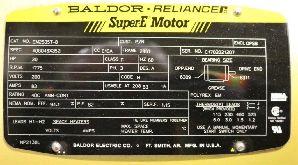
Example of an electric motor nameplate adhering to NEMA standards.
The following information is required to be listed on nameplates by NEMA:
Frame Designation (FR) – Usually a two or three digit number followed by one or more letters that serves to identify important mounting dimensions.
Manufacturers Type (TYPE) – Manufacturers use TYPE to indicate a product family or some other attribute that identifies the motor’s fit or function, such as single-phase/poly-phase or type of construction. There is no industry standard for the TYPE designation.
Horsepower Output (HP) – Typically listed as HP by NEMA standards (kW by IEC standards), this is the measure of the motor’s ability to deliver the torque required for the load at a rated speed. The standardized NEMA table of motor horsepower ratings runs from 1 hp to 450 hp. When an application’s horsepower requirement falls between two standardized values, the larger size is usually chosen.
Horsepower (HP) = [Motor Speed x Torque (lb-ft) + 5250]
HP = 0.746 x kW
kW = 1.34 x HP
Time Rating or Duty (DUTY) – This parameter specifies the length of time that the motor can safely carry its nameplate rating. This designation can be continuous (listed as “CONT” or “S1”), which is defined by NEMA as “indefinitely”, or intermittent, usually expressed in minutes. If no designation is indicated on the nameplate, the motor is designed for duty cycle S1.
Max Ambient Temp (AMB) – This is the maximum allowable temperature of the surrounding air to ensure that the motor can operate within the tolerance of the insulation class at the maximum temperature rise (the heat generated at fully loaded conditions). If no ambient temperature is listed, the standard ambient temperature of an EFF2 motor is 40 °C (104 °F) and 60 °C (140 °F) for EFF2 motors. Note: EFF is a measure of energy efficiency, with lower class numbers representing higher motor efficiency.
Insulation System Designation. (CLASS, INS. CLS., INSUL CLASS) – Insulation class is an industry standard classification of the thermal tolerance of the motor winding. The insulation class is determined by a variety of factors, including the ambient temperature, the heat generated at fully loaded conditions (temperature rise), and the thermal capacity of the motor insulation. Classified as A, B, F, or H, the letter designations indicate the thermal tolerance, or the winding’s ability to survive a specified operating temperature for a specified period of time. Note: Insulation classes perform better as you get further into the alphabet. For example, Class H insulation has a longer nominal life at a given temperature than class A, or for a given life it can survive higher temperatures.
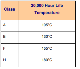
Insulation Classes are based on adding the ambient temperature and the operational heat created by the motor.
Full Load Speed (RPM) – This is the approximate speed at which the motor will operate under full-load conditions, when voltage and frequency are at the rated values. An induction motor’s speed is always less than synchronous speed, and drops off as load increases. The synchronous speed (S) is the theoretical speed of a motor based on the rotating magnetic field.
S = (120 x F)/P
S = Speed in RPM
F =Frequency in hertz
P = Number of poles in motor
On standard induction motors, the full-load speed is typically 96-99% of the no-load speed. This difference is known as slip, or slip-RPM. For example, a motor with a synchronous speed of 3600 RPM will have an actual speed of about 3450 RPM, and a slip of ~150 RPM.
Frequency (HZ) – The standard frequency in North America is 60 Hertz (Hz, cycles per second), and usually 50 Hz elsewhere. If the nameplate shows more that one frequency, it should also display frequency-dependent characteristics for each. If the motor is designed to operate at varying speeds using a variable frequency drive (VFD), then a frequency range is typically given. NEMA allows motor frequency variation of only +/- 5% for non-VFD applications.
Number of Phases (PH) – Indicates the number of AC power lines supplying the motor. Either single-phase or 3-phase motor.
Rated Voltage (VOLTS) – The voltage at which the motor is designed to operate and yield optimal performance. Other parameters defined on the nameplate such as power factor, efficiency, torque, and current are at rated voltage and frequency. Use at frequencies and voltages not on the nameplate will likely result in different performance. Motors are designed with a 10% tolerance for voltage above and below the rated value on the nameplate. For example, a motor with a rated nameplate voltage of 460V would be expected to operate between 414V and 506V, though performance may be diminished.
Full Load Amps (FLA, AMPS) – When the full-load torque and horsepower is reached, the corresponding amperage is known as the full-load amperage (FLA). This value is determined through lab tests, and is rounded up slightly and recorded as the nameplate value in order to voltage and manufacturing variations. The nameplate FLA is used to select the correct wire size, motor starter, and overload protection devices necessary for protecting the motor.
Locked Rotor kVA Code (CODE) – When AC motors are started with full voltage applied, they create an inrush current that is usually many times greater than the value of the full-load current. The value of this high current can be important as the resulting voltage dip may affect other equipment. The start inrush current has been standardized and defined by a series of letters (ranging from A to V) which group motors based on on the amount of inrush in terms of kilovolt amperes (kVA). Generally, the farther the code letter is from A, the higher the inrush current per hp. A replacement motor with a higher locked rotor code may require additional upstream electrical equipment, such as a larger starter.
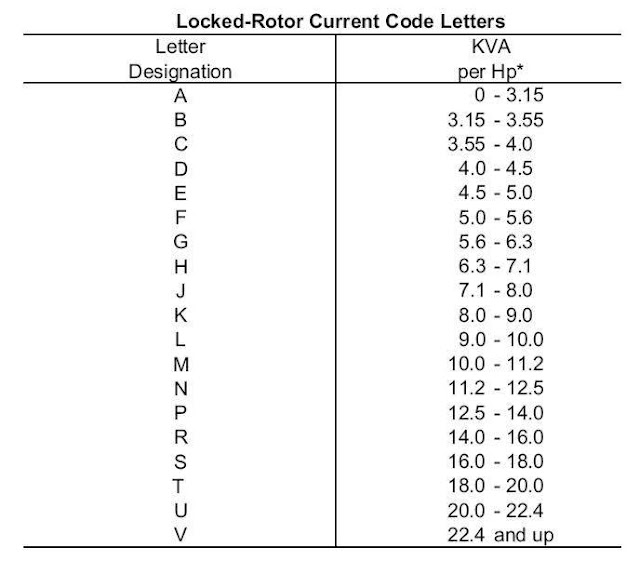
Table showing the Locked Rotor Current Code Letters and the corresponding kVA/hp
Design Letter – NEMA defines four motor designs (A, B, C, and D) in terms of torque and current characteristics. See the tables below for more information.

Table showing NEMA Design Letters and their characteristics
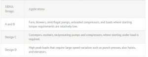
Table showing NEMA Design Letters and their applications
Nominal Efficiency (NOM EFF) – Efficiency is the ratio of the power output divided by the power input. Expressed as a percentage, efficiency indicates how well the motor converts electrical power into mechanical power. NEMA requires nameplate efficiency to be a nominal value based on the average of a large group of motors of the same design. The actual efficiency of any one motor must be within a tolerance band based on a +/- 20% variation in motor losses.
Service Factor (SF) – Motor Service Factor is the percentage of overloading the motor can handle for short periods when operating normally within the correct voltage tolerances. The industry standard service factors are 1.0 for totally enclosed motors and 1.15 for open drip-proof (ODP) motors. Most manufacturers now offer totally enclosed fan cooled (TEFC) motors with service factors of 1.15, though, and service factors of 1.25, 1.4, and higher exist. Note: The service factor is only required to appear on the nameplate if it is greater than 1.0.
Power Factor (PF) –The ratio of active power (W) to apparent power (VA), expressed as a percentage. It can vary from 0 to 1 depending on load conditions, usually reaching a peak at or near full load on the motor. It is desirable to have high power factors close to unity (100%). The power factor can be improved by adding capacitors.
Thermally Protected (THERMALLY PROTECTED) – The words “THERMALLY PROTECTED” are required to appear on the nameplate if the motor provides all the protection described by NEMA standards.
Over Temperature Protection (OVERTEM PROT) – For motors rated above 1 hp equipped with over temperature devices or systems, a number from NEMA must be inserted in the blank to identify the protection type.
Other Information You Might Find on a Nameplate
Nameplates may also include information about bearings, characteristic curves, altitude limitations, and more. If you’re unsure of the meaning of information found on your electric motor nameplate, consult the manufacturer’s resources or reach out directly. An understanding of the information displayed on the nameplate is a crucial part of the operation and maintenance of electric motors.
Electric Motors at Iron Wing
Looking for electric motors or related parts? Iron Wing has a large inventory of electric motors and related industrial electrical parts for all of your needs. Genuine parts from Siemens, Leroy Somer, Baldor, WEG, and many more manufacturers. Already know what you’re looking for? Use our product search, or reach out to our sales team via email at sales@ironwingsales.com

